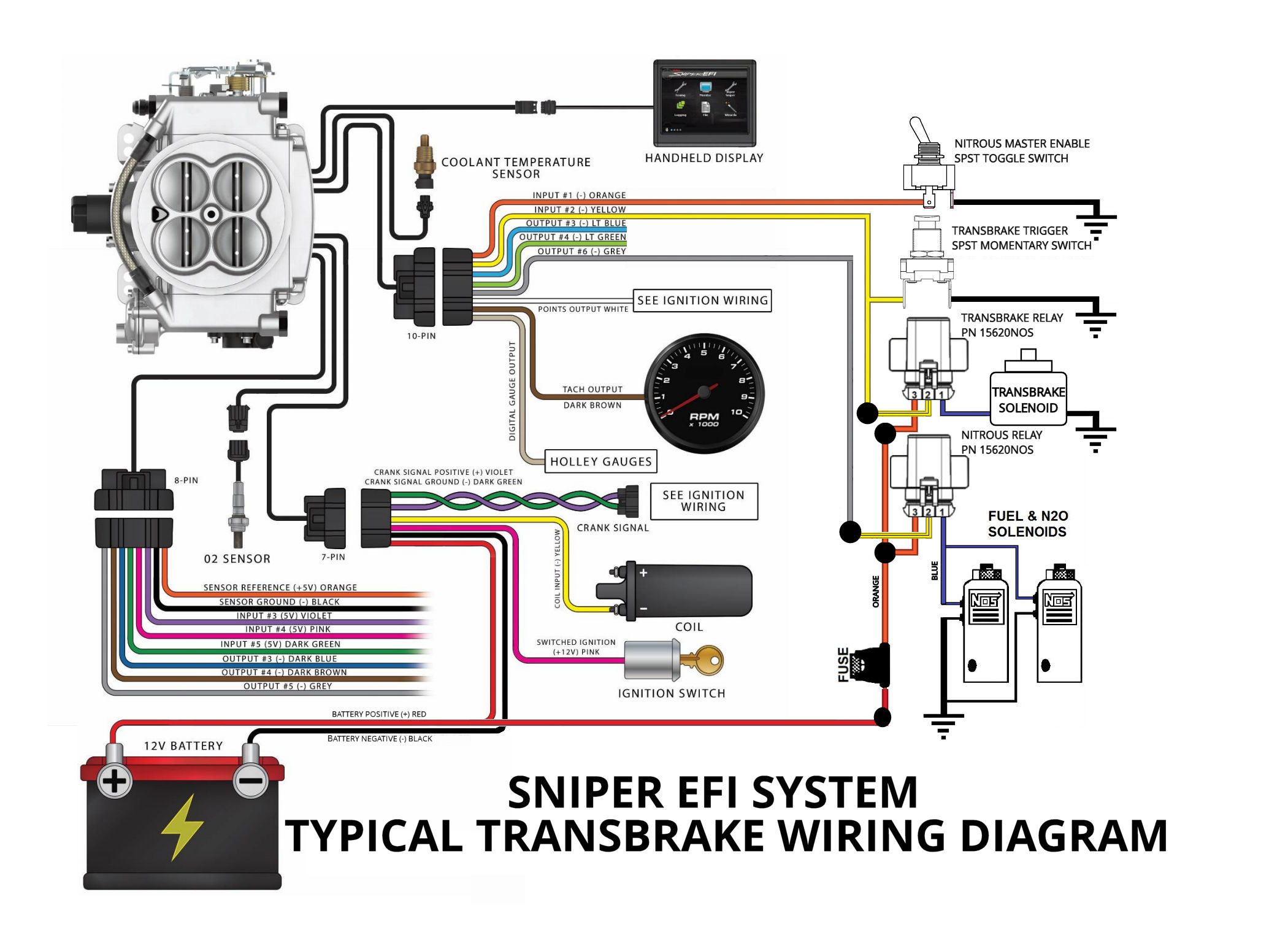
Fast Efi Wiring Diagram
Fast man efi technical information on this page i will post documents, notes and videos pertaining to the fast efi systems. After installing the circuit the communication error is almost fully eliminated and the handheld is programming the ecu correctly.
Wiring harness "our instructions have evolved to the point where we have practically no questions from the enthusiasts doing the work in their garage," says maxwell.

Fast efi wiring diagram. The msd hei inductive ignition module only had 3 degrees of dwell at idle until the fan came on and dropped the voltage a bit then the dwell went up to 4 degrees and that was enough for the tach signal decoder module and efi to get a rpm signal pulse that it. #3 green with orange wires. Your mastercell input for the fuel pump trigger will connect to the fuel pump control output on the fast harness.
It shows the components of the circuit as simplified shapes, and the skill and signal links along with the devices. The 1n4001 wire should be installed per our wiring diagram. This wire provides +12v only at crank.
The first step is clearing away. #1 black with orange wires. If you get stuck or need clarification, sing out.
But the ecu will be damaged and system performance will degrade. Fast powerhouse products racing head service tci auto zex home products power packages efi systems ignition intake manifolds fuel injectors air/fuel meters merchandise efi components distributors throttle bodies fuel systems transmission controllers tools tech center technical resources writing diagrams technical articles other software downloads You won't need the rf blue (efi crank) wire.
We actually finally found a wiring diagram somewhere on the dark webz and all was good. We have replaced the impeller, oil pump, oil control module and 2 rectifiers and still are hearing the alarm. We understand this nice of fast efi wiring diagram graphic could possibly be the most trending topic taking into account we portion it in google improvement or facebook.
Efi™ wiring harness directly to the negative side of the coil. This is the black wire at cavity b5 on the fast harness. The solution is to insert a wire parallel to the ecu to ground containing a ceramic capacitor.
We identified it from honorable source. My fast efi is installed and the harness has the following wires to. The rf tan (electric choke) wire provides +12v at acc and run.
We've been tuning and selling fast efi systems for over 20 years. Obviously you will probably have questions so don't hesitate to email me. It is important that you install the diodes that are shown in the diagram.
Deltrol 53akit, ez efi base tbi system (does not include pump/regulator kit) system features: Fast is the leading developer of electronic fuel injection systems, efi components, intake manifolds, tuning tools for high performance and street. More › 225 people learned
1993 jeep wrangler 4wd 4 0l fi ohv 6cyl repair guides multi point fuel injection mfi system troubleshooting au jeep wrangler jeep cherokee sport jeep from www.pinterest.com. Just like the cooling fan input, the diode should be wired per our wiring diagram. Here's a document that should help.
#7 · jun 25, 2013. Here are a number of highest rated fast efi wiring diagram pictures on internet. Its submitted by organization in the best field.
Our recommendation is to use a 1n4001 diode. It may actually start up and run that way. Terminate it so that the wire can't short to ground.
10 170665 loom, braided wire split 2 170666 ring term, 12‐10 awg, 3/8 stud, shrink 1 170667 hex key, 4mm long arm reach 1 170669 butt splice, 14‐16 awg, shrink 1 170655 badge, fast ez‐efi chrome 4 54023c fitting, fuel ‐8sae o‐ring to ‐6an 1 54023d plug w/o‐ring, ‐8sae Al, i did not see a link in the above posts for the ez efi. #2 yellow with orange wires.
A wiring diagram usually gives information very nearly the relative viewpoint. Ecu, wiring harness & interface module. The cd box fixed it.
If you just need the hookup for the injectors, they all have a colored wire, with an orange wire attached to the plug. Please note that the orientation of the diode is important. Attached is a schematic, but it may be hard to read.
The motor starts right up and idles perfectly but does not seem to have much power upon acceleration. May 29, · we begin with a basics fuel pump & relay diagram.
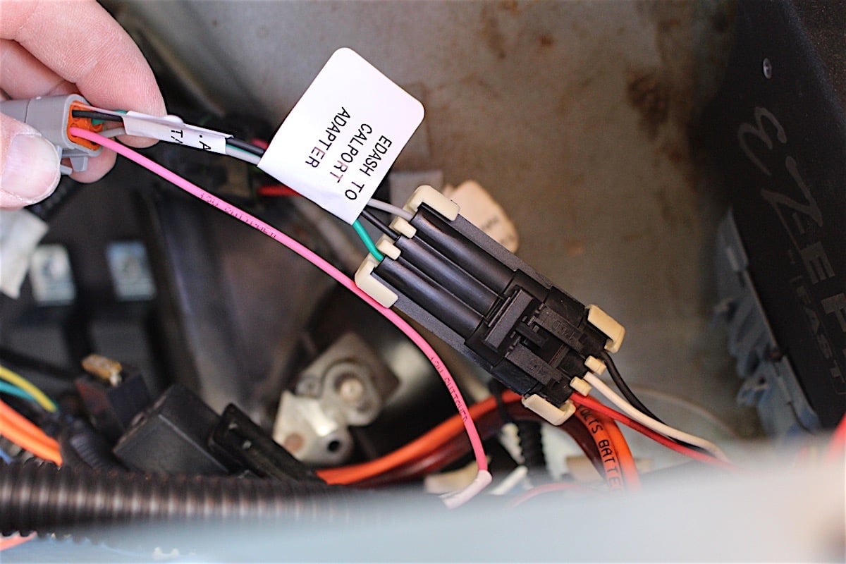
Installing FAST's EZEFI Fuel Injection System EngineLabs

Fast Xfi 2.0 Wiring Diagram Wiring Diagram And Schematic

Installing a FAST EZEFI and Inglese's 8V Induction System

Fast Ez Efi 1 0 Wiring Diagram Wiring Diagram and Schematic

Wiring the FAST EZEFI Infinitybox

Fast Xfi Wiring Diagram Wiring Diagram & Schemas

FAST EZEFI FullColor Handheld Upgrade You'll Want To Do

Fast Ez Efi 1 0 Wiring Diagram Wiring Diagram and Schematic

Holley Hp Efi Wiring Diagram General Wiring Diagram

EFI System Electronic And Mechanic
Ez Wiring 20 Diagram Wiring Diagram & Schemas


